
Making the crude oil refining industry sustainable – water and wastewater treatment technologies
Generally, the water is collected from a water source close the refinery and, after the adequate treatment, distributed to consumption according to the final application. Normally, the use of water in a refinery is divided as water to fight emergencies, clarified water, industrial water, potable water, and demineralized water. Figure 1 presents a simplified diagram of the treatment processes and the water streams produced.
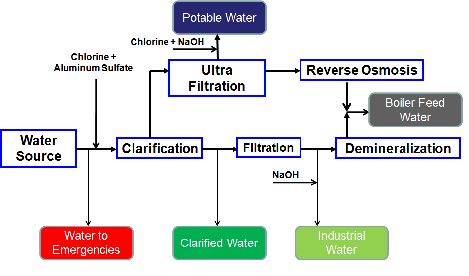
Figure 1 – Simplified Process Flow Diagram to the Water Treatment Processes in a Crude Oil Refineries
The raw water is collected and sent to a treatment station in the refinery. The portion of the water used to supply the emergency network normally doesn’t receive any treatment, being basically composed by the raw water. Before the clarification step, the water receives the dosage of chlorine aiming to promote the oxidation of organic compounds and aluminum sulfate to favors the coagulation of suspended particles. Clarified water is normally applied to make up the cooling towers of the process units and as a feed stream to the filtration and ultrafiltration steps. After the filtration steps (normally carried out in sand filters), part of the water stream receives a dosage of caustic soda aim to control the pH between 7,5 to 8,5, this portion of the water is called industrial water and is used directly in the process like washing water in crude oil desalters or reactors decoking fluid in delayed coking units.
The potable water receives an additional treatment with chlorine aiming to disinfection and caustic soda injection to keep the pH in the range of 7,0 to 8,5 and is applied in general use in the administrative and industrial areas of the refinery.
The ultrafiltration process applies membranes with pores in the range of 0,01 to 0,001 µm capable to promote the separation of the major part of viruses, bacteria, and high molecular weight compounds. After the ultrafiltration step, the filtrated water passes through the reverse osmosis step that applies membranes even more selective capable to remove particles in the range of 1 to 10 angstroms, posteriorly the water is applied to feed boilers which will produce steam to the process as well as the stream of demineralized water.
The demineralization process is composed by beds of activated carbon aiming to remove the chlorine from the water to avoid damage to the ionic exchange resins, posteriorly the process uses vessels filled with polymers chemically actives that promotes the exchange of the ions between the resin and the water to be treated like described in Figure 2.
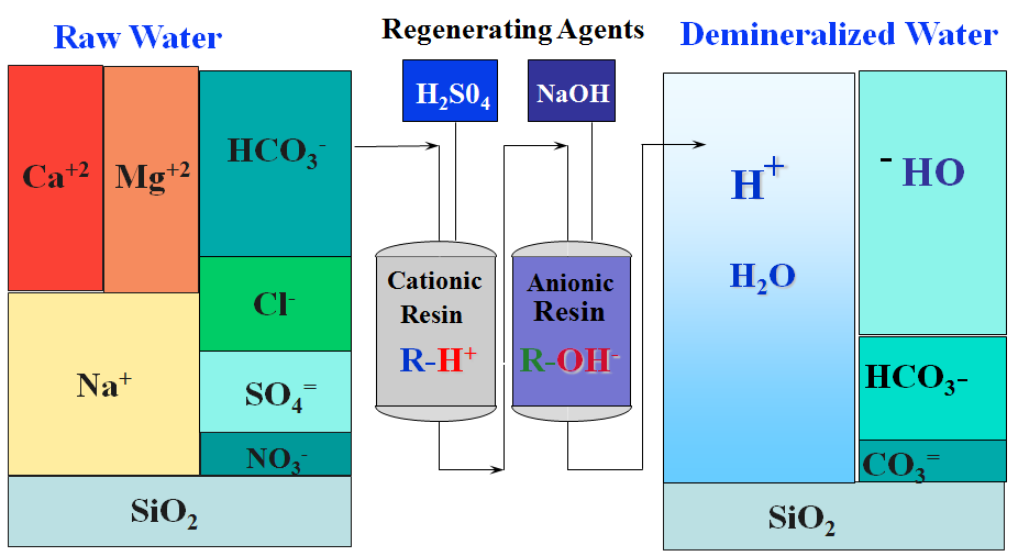
Figure 2 – Demineralized Water Production Process
The process is based on the substitution of ions from the water stream by equivalent quantities of ions with the same electric charge by the resin. The demineralized water, as well as the permeated water (from the reverse osmosis), can be applied directly as boiler feed water. The quality parameters controlled in the boiler feed water are pH (8,5 to 9,8), conductivity that is controlled bellow of 1,5 mho, and the silicon content that can’t be superior to 0,05 ppm.
One of the most relevant issues for refiners in recent years has been the reduction of water consumption in processes. The lower water intake for industrial applications, besides reducing the operational costs of the refiners, allows more water to be available for nobler purposes such as human consumption. This fact is relevant mainly in regions where there is a lack of good quality water.
One of the most important steps in the crude oil refining process is the treatment of effluents generated during the process of adding value to the streams that will make up the pool of derivatives.
As important to the operational continuity of a refinery as an efficient water treatment is a process of treating the wastewater. Environmental norms around the world are increasingly restrictive. These currents have high levels of contaminants, some of them being carcinogenic like the aromatic compounds. Most of the compounds are organic (hydrocarbons, nitrogenated, sulfurous) or ammoniacal and consume a large amount of dissolved oxygen altering life conditions in these environments. Figure 3 presents a process flow diagram for a typical wastewater treatment station.
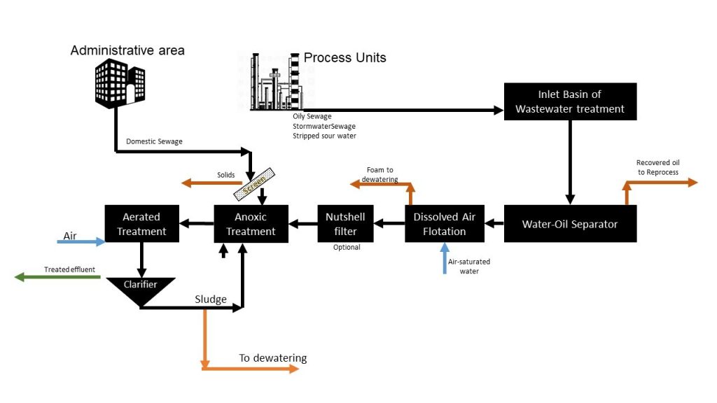
Figure 3 – Wastewater Treatment Station with Activated Sludge Reactor
In addition, the water balance of the refinery will be carried out by the effluent stream and the total flow will be limited by the treatment capacity of the wastewater system. With this important restriction, any increase in water consumption should be studied considering this premise. On the other hand, current technologies allow the removal of contaminants with such efficiency, that the reuse of treated streams, is now a reality. The equation of cost of reuse vs. cost of raw water should always be considered, however, this ends up being a matter of preservation of a limited resource in practically all regions of the planet.
Oily Sewer
The wastewater streams of a refinery are produced from virtually all processing units. In the distillation unit, the desalting of crude oil precedes the separation process. In this process, water is injected and oil is subjected to the electric field so that the salts and sediments are passed into the aqueous phase (brine) and are sent for treatment. This stream is composed of water, salts, sediments. The first step of this treatment occurs in a tank with a residence time sufficient to allow separation of the oil phase. The aqueous phase will be treated at the industrial wastewater treatment plant.
Still, in the distillation unit, there is the injection of steam for the rectification. After the cooling of the derivative streams, the steam is condensed and collected as sour water and sent to treatment in a specific process unit (Sour Water Stripping). The treated stream can be reused in the processing units, with the surplus being sent to the wastewater treatment plant. In the units of catalytic cracking, delayed coking and hydrotreatment there is also the generation of sour water that is sent to the same type of treatment.
Cooling towers need to have a limited salt concentration to prevent corrosion or fouling in heat exchangers and piping. This control is done by chemical dosing and purge.
Stormwater sewer
The streams mentioned above are continuous and independent of climatic events. In rainy situations, there is also the contribution of the stormwater sewage system of the ground of processing units that are water contaminated with hydrocarbons. For this reason, the treatment plants are designed with a capacity of 50% higher than the volume of effluents expected in dry weather.
The stormwater sewer system is an open-channel network and covers the whole refinery. Rain and stormwater are collected inside the dikes of the storage tanks or in a specific tank and drained to the ETP network.
Domestic Sewage
All the sanitary from toilets and canteens in the refinery (including the administrative building) are connected to this system. This connection is made partly by gravity and partly by pumping.
Steps of Effluent Treatment
The wastewater of oil refining industries is typically biodegradable. The standard scheme of a treatment unit is designed based on physical-chemical processes as primary treatment focusing on free oil and sediments removal, a biological treatment (aerated, anoxic and/or anaerobic treatment). As a polish treatment, some designs have a microfiltration membrane at the end of the process or dosing an oxidative chemical, like hydrogen peroxide.
The wastewater is routed to the first stage of the treatment to the removal of free oil. The typical concentration of oil and greases can range from 100 mg / L to 1000 mg / L. The equipment responsible for this step is known as the water-oil separator.
API Oil-Water Separator
This is a standard device for separating oil in refineries. The separation is based on the difference in density between the water droplets of suspended oil and the solid particles, creating a three-phase system. The oil collected on the surface and sent for reprocessing. The solids are collected on the bottom for further dewatering device like centrifugal dewatering. The aqueous phase, which still contains oily emulsified material, follows for treatment in a flotation process.
Dissolved Air Flotation
Minor oil droplets and very small particle sediments cannot be removed by density difference and require a driving force for efficient removal. A traditional process in oil refineries is the dissolved air flotation. In this device, there is a dosage of a chemical to break the emulsion, usually aluminum sulfate, ferric chloride or other electrolytes capable of inhibiting repulsion between the particles promoting coagulation. With the formation of flakes, it is possible to inject air-saturated water at the bottom of the float, with the reduction of pressure the air is released forming small bubbles that drag the flakes to the surface forming a foam that is removed and sent to dehydration system. The clarified water is sent to biological treatment. Some designs have a nutshell filtering device focusing on oil removal to avoid foam on the aerated treatment.
Biological treatment
After oil and sediments removal, biological treatment of wastewater is done under aerobic condition (excess of free Dissolved Oxygen) for reduction of carbon-based organic pollutants and ammonia. The aim is to enhance microbial oxidation of the organic and ammoniacal pollutants using the naturally occurring bacteria in the environment. These bacteria consume the major part of the organic substances as energy and mass source while converting the pollutants into new cells and harmless compounds. By the same way, ammonia is converted to cell proteins and Nitrates/Nitrites in wastewater bulk.
Inactivated microbes result in sludge that must be removed periodically to maintain the treatment activity.
The basic biochemical reaction for the stabilization of organic and ammoniacal impurities under aerobic condition by microorganisms in wastewater may be represented by:
Organic impurities + Ammonia + microbes + O2 ->Microbes + Nitrite + Nitrate + CO2 + H2O + waste energy
Nitrite and Nitrate are toxic substances and must be removed before discharging. In anoxic conditions, denitrifying bacteria use the organic compound as food but uses Nitrites and Nitrates as an oxygen source. This way, molecular nitrogen is released to the atmosphere as a product of the reaction.
Organic impurities + Nitrate + Nitrite + microbes->Microbes + N2 + CO2 + H2O + waste energy
In aerated systems, bacteria and protozoa are mixed with wastewater and motor operated aerators or air blowers feeds with air. In anoxic systems, aeration is minimum. The bacteria water (mixed liquor) is then sent to the clarifier where the microbial mass is separated from the water. The bacterial mass returns to the bioreactors to maintain the required level of microbial cell concentration. The rest of the bacteria may be sent to the biological sludge centrifugal dewaters and after disposal. The water from the clarifier unit goes to the treated water pool, ready for disposal or reuse based on the final quality.
Membrane Bioreactors (MBR)
Membranes are semi-permeable barriers is highly efficient in separation and purification of components is amply evident throughout nature. Living cells use the screening properties of membranes to collect and eliminate substances. Since the 1970´s this screening properties have been used to numerous applications of membrane-based technology in separation and purification. A typical treatment station with MBR is presented in Figure 4.
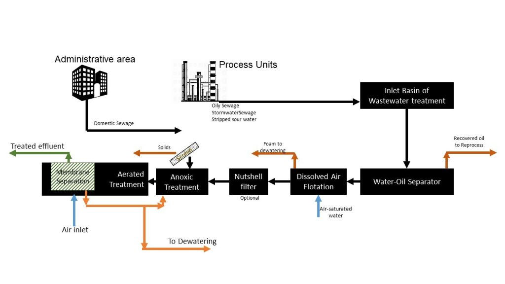
Figure 4 – Wastewater Treatment Station with MBR Reactor
With the increased availability of membrane of versatile materials, the possibility of integration of membrane separation with conventional treatment nowadays is a reality. This type of membrane-integrated approach in refinery effluent treatment is culminating in novel treatment plants with a high degree of process intensification resulting in safer, more flexible, more compact, and economically viable green processing treatment units.
In this type of plant, the clarifier is substituted by a set of membrane modules which objective is separate the sludge from the treated wastewater. This scheme permits a higher quality of final effluent with large possibilities de reusing. The membranes may retain bacteria, viruses and minor sized solid particles. Removal of 95% of COD and 99% of ammonia can be easily achieved. Typically the final effluent of a treatment plant oil refinery wastewater has low COD, BOD, and ammonia. However, the quantities of soluble salts may present high values. To reuse this water in steam generating, before a process of demineralization is necessary desalination like reverse electrodialysis (RED).
Process sustainability is critical not only to the crude oil processing chain but to any industrial activity. Maintaining the integrity and reliability of these processes is a key factor in ensuring the competitiveness and permanence of refiners in the market in compliance with environmental requirements.