
The parts that a typical DAF system should contains:
A typical DAF system should includes:
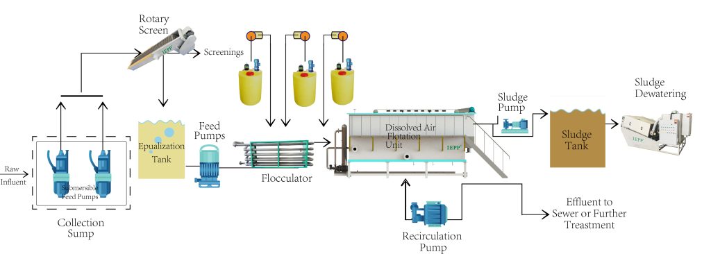
1. Screening
Adequate screening to remove gross solids from trade waste influent, buffering and treatment steps is crucial as it: Prevents solids blocking/damaging wastewater feed pumps, DAF recycle pumps and sludge pumps. Limits odours produced by anaerobic degradation of settled sludge that build up in the DAF unit and buffer tank. Reducing the build-up minimises the need for complete vessel clean out. Minimises sludge formation over the aeration bars in the DAF unit, which could otherwise upset micro-bubble formation. Reduces coagulant/flocculant consumption (if used at a later stage) by first removing as many solids as possible by simpler means.
A variety of screening mechanisms is available. Careful matching of the design and hole/mesh size with typical particle size and other wastewater characteristics is necessary. Rotating drum/sieve and bow shaped wedge-wire screens are commonly used. In retail food preparation/service areas, silt trap baskets are useful for preventing localised drain blockages, but are not an acceptable mechanism for screening before a DAF. A centralised screening mechanism with maximum 1mm hole/mesh size for processing all wastewater destined for DAF treatment is necessary.
2. Buffering / holding tank
Ensuring the influent is as consistent as possible over a production period or daily DAF operating cycle is crucial for optimum DAF performance. Collecting screened wastewater in a buffering/holding tank for a sufficiently long period before further treatment moderates short-term variations in quality. The key parameters to be moderated are:
Temperature
Elevated temperature or hot ‘slugs’ of material can emulsify G&O resulting in a higher percentage of carryover through the DAF unit, hinder the supply of dissolved air and promote undesirable biological breakdown of material in the DAF unit. Temperature in the DAF vessel should be maintained below 40 degrees C.
pH
pH inconsistencies can result in potential damage to treatment equipment, odours and non compliance with the trade waste discharge limit of pH 6-10 at all times. Buffering of pH by mixing acidic and alkaline discharges might eliminate the need for chemical pH correction, or reduce alkali/acid dosing costs and their undesirable Total Dissolved Solids (TDS) impact.
Solids
The recycle volume and air settings are set manually, to arrive at the desired air to solids ratio in the DAF vessel. Similarly, the dose rate of flocculant (floc) or coagulant (coag) is set to efficiently treat a certain concentration of contaminants. The DAF unit cannot automatically vary the settings to accommodate wide fluctuations in wastewater quality. Solids carryover to sewer is likely if higher than expected concentrations of solids enter the unit. Buffering moderates variations in wastewater solids concentrations and is a better alternative to adjusting the ongoing DAF settings, for effectively coping with short-term high contaminant concentration events. Careful investigation of wastewater quality and flow variations is needed to arrive at an effective buffering/holding tank capacity. The minimum capacity varies significantly between individual applications, particularly industrial sites. However, a typical minimum buffering tank capacity of 4 hours at design peak influent flow rate is required for centralised retail applications.
Other Buffering Considerations
Appropriate mixing of tank contents ensures that solids and fats do not separate out, and tank contents remain aerated to minimise odours from biodegradation of waste before treatment. Extra contingency capacity in buffer tank storage is advisable for emergencies (e.g. DAF unit maintenance shutdown, sewer unavailability). It also allows for increasing the normal operating levels, if required to achieve the desired buffering of wastewater. However, holding wastewater for excessive periods due to overly generous buffering capacity or delays in processing wastewater can lead to degradation of influent, odours and lower wastewater pH.
During low flow periods, the buffering volume should be adjusted accordingly. During prolonged shutdown periods, it is advisable to process the buffer tank contents through the DAF unit and have the sludge from the buffer tank and DAF cell hauled off site.
Pre-reaction and pre-treatment tank volumes can be included as volume toward the minimum buffering requirement.
3. Pre-treatment
Aside from screening, further pre-treatment is not generally required for retail food service applications. In some industrial situations, it may be advantageous to install various forms of pre-treatment before DAF – to minimise DAF operating costs, maintain consistent loadings to the DAF unit, or target removal of contaminants not primarily suited to air flotation. For example:
An oil water separator can be used to remove free oil (and solids at low levels) for minimal cost before DAF treatment.
A clarifier/settling tank can minimise solids loading to the DAF unit, by gravitational separation. This is especially useful for capturing grit and other rapidly settling solids that would cause settled sludge deposits in the DAF unit.
4. pH correction / chemical addition
pH correction systems must be installed on all DAF units, unless sufficient evidence verifies that this is not necessary. In retail applications with adequate buffering, alkali dosing is usually necessary (to increase pH). This is primarily due to the natural tendency for highly biodegradable wastewater to decay before all on site treatment steps are completed. Poor treatment system design and operation can compound on this tendency. Acid dosing to lower pH will not generally be required.
pH control of DAF treatment systems is essential for:
Ensuring pH complies with discharge limits.
Ensuring pH is within the ideal range for floc/coag effectiveness.
Minimising grease/oil emulsions.
Where the removal of targeted contaminants with DAF alone is poor, a flocculant and/or coagulant may be required. They assist in the separation of solids/fats from the water, and can greatly increase the removal efficiency of the DAF unit, or allow it to effectively cope with heavier contaminant loads than originally envisaged. A wide variety of chemicals are available, requiring specialist selection to arrive at the best balance between cost and effectiveness at each site.
Chemical addition is generally not required in retail applications provided influent is consistent, low in temperature and emulsified grease/oil.
Provision should be made at the outset on all DAF installations, for possible future inclusion of chemical addition (e.g. bunding, space for a pre-reaction chamber, flow meter & PLC compatibility).
5. Pre-reaction tank
Pre-reaction tanks (well-mixed vessel on the influent side of the DAF unit) are not generally required for retail operations, but are common in treatment of industrial trade waste. Pre-reaction tanks assist in mixing chemicals for pH correction, floc/coag addition. A pre-reaction tank provides adequate retention time to ensure optimum contact with chemicals before aeration. This is vital when using clay or bentonite-based floc/coag additives that require increased reaction times to achieve the most effective separation. The use of pre-reaction tanks can minimise chemical costs and unwanted increases in final TDS concentrations.
Although an adequately sized buffer tank is preferable, a pre-reaction tank provides additional buffering before DAF treatment in circumstances where buffer tank sizing may be restricted.
6. DAF units
DAF units with ‘hopper’ or conical bottom sections on the main DAF vessel are advisable when there is likely to be significant loadings of grit, clays, silt and any other solids likely to sink rather than float in the DAF vessel. This design simplifies removal of settled sludge.
Plumbing into and out of the DAF unit should prevent any syphoning, or any significant changes to DAF operating water level. Otherwise, higher level surges could cause water carryover in the scraped sludge, and floating solids removal would not occur with a drop in level below the scraper blade and sludge ‘beach’ positions.
It is vital to maintain flow and consistent contaminant levels into the DAF unit, within its practical operating limits.
All feed pumps must be of the non-emulsifying type (e.g. diaphragm or progressive cavity “Mono”).
Relief of dissolved air into the DAF unit should be through an appropriate self flushing valve with broad seat clearance. Manual valves (i.e. ball valves) must not be used in an attempt to maintain constant dissolved air feed to the DAF unit, as they are likely to partially block and result in turbulent large air bubbles. This decreases the performance and reliability of the DAF unit.
7. Sludge/screenings disposal
DAF units, screening and pre-treatment mechanisms are likely to produce a significant quantity of sludge for off-site disposal. The quantity can be predicted with reasonable accuracy if the untreated wastewater quality and quantity is known. These calculations will determine final sludge tank sizing.
A de-watering device is a practical necessity for almost all DAF systems, to reduce the quantity of solids to be hauled off site.
Appropriate organic floc/coag additives are desirable, due to increased scope of disposal options, such as composting instead of landfill.
8. Monitoring/metering requirements
Process control
pH correction probes used to ensure compliant discharge and optimum DAF performance must be placed upstream of main DAF unit in a location exposed to representative wastewater flows. Suggested locations include; pre-reaction tank or a well-mixed buffer tank. pH control probes should NOT be located in main DAF vessel, unless careful consideration has been given to their ability to accurately maintain compliant discharge at all times. Probes should be of suitable quality and design appropriate for the particular wastewater type.
Final effluent monitoring
Effluent flow meters are required on all DAF installations.
Electronic monitoring of final discharge quality
Monitoring of final pH, TDS, etc may also be required. Electronic probes must be in a location exposed to representative final treated trade waste discharge. Recommended locations are:
a flooded section of pipe work immediately downstream of the DAF unit,
the effluent weir overflow (if flows are uninterrupted), or
in the main DAF cell against the effluent weir near its overflow.
Data collection and alarms
These may also be required.